The fable of f
A true story...
This model is probably one of the most profound machines I have ever constructed.
It is a reconstruction of Tesla's 1896 RF work and relies on the notion of coupled-circuits
to couple the electric energy input at the BNC terminal to a magnetic field at the
secondary. In more complicated versions of this, first-order magnetic fields can
be generated, something I have not ever seen in any other physical device,
only in the theory. What this means in real terms is that you can send a wireless-power
signal 10 meters easy without any appeciable losses.
In March 2004, I redesigned Tesla's wireless generator patent of 1897. I dubbed
it "Model F Wireless Power Generator" as a tribute to Tesla's
work and its designation 'F' as one in a long series of prototypes which
came before. But the Model F differed significantly from Tesla's. Firstly,
my device was not nearly the size of the original machine and secondly I altered
a part of the design to facilitate the use of an ancillary device, the i-Cybie robot
(Figure 4). One significant advantage of being 100 years in the future, I was able
to use modern materials to construct the device. I used cheap, off-the-shelf, easily
available parts such as plastic storage containers for the spiral coil mounts, wooden
dowels for the upward antenna, and scrap circuit cards to mount the components specific
to my design. To transmit the power on the board, I used hobby brass which was easy
and cheap to obtain from the local train shop. Thinking of the energy as a wavelike
flow, I employed brass tubing shielded with aluminum to contain the power away from
the receiving coil. In past research I learned that paramagnetic materials were
best to delay the synchronization of the electric and magnetic with the inductive
components of the wave along the linear time vector. I was thinking of the wave
in all three dimensions E, I, and H traveling simultaneously at right angles to
each other. In order to manipulate such a wave, I discovered from research with
the Model C2 (Figure 3) that if I could change the rate (or relational phase) at
which the vector H was transmitted with the other two x two components--frequency
and amplitude x (frequency and amplitude)--keeping these two locked in phase,
they could be compressed along the time vector allowing more power to be transmitted
in a smaller space while floating the magnetic potential A in a
quasi-linear state. There was an opposing force observed when implementing this
design. When compressing the two vectors, opposing force electrons would appear.
They assumed the opposite charge in the system, categorized as positrons. These
positrons cause in an internal oscillation pattern inside the wave agianst the electrons
as their motion keeps them from annihilating each other. This point is where I need
to do more research and where the heart of the analysis lies. Hypothetically speaking,
however, such a solution suggests there is a method to directly effect the physical
state of the wave's geometry like a raw material to fabricate different energy systems.
Tesla's design transmitted power from transmitter (Tx) to receiver (Rx) only.
Both systems used rather large spiral coils (around 40cm in diameter) and were too
large to be hauled around by the robot. I wrote a series of equations whereby I
could use a linear-wound coil mounted on the upward dowel shaft in the center of
the spiral in agreement with the operational band of the tuned system. This meant
there was a third component of the design; power would travel in the same manner,
from spiral A to spiral A', but the magnitude of the energy was shifted in
phase to the ancillary card onboard the Cybie (Figure 5). The operational frequency
was set to around 68MHz, the amplitude to 24VAC, which was more than enough power
to provide 18VDC (once converted by the card) necessary for the robot's operation.
Operational threshold as of April 2004 is 100VAC.
The upward linear coil was wound with careful note as to the direction of the wind
so I could wind a twin oppositely in agreement with Tesla's spiral design. The twin
was mounted onto a card cut to fit inside the Cybie's battery compartment. There
was enough room to fit components onto the board to do the necessary DC conversion
of the incoming signal. For all intrinsic purposes the Cybie was ready for test.
This unit is a handbuilt capacitor set to the operational frequency of the device.
It took about three weeks to construct the apparatus on my porch in Utah. It caused
much dismay in my neighbors when they discovered what I was building. I think they
were more confused as to my labors more than anything else. I never bothered explaining
the machine to many people, most were unsure of what a wireless power device was
much less of the implications. Regardless, the machine functioned as expected and
had performance much greater than the equations I had written to describe it. I
suspect there is more going on than meets the eye.
Sometime during April to May 2004, I sat down and recorded with the only camera
I could afford at the time, some of the experiments.
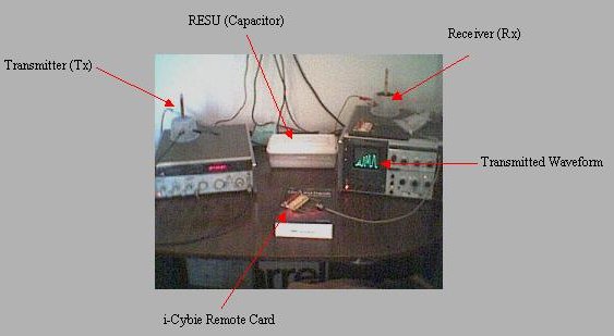
Figure 1: Experimental Broadcast Test
The device tested positive for modulation transmission (AM and FM).